
n the realm of electrical engineering, understanding power factor is crucial for efficient power management and optimization. Power factor, a key parameter in AC electrical power systems, directly impacts the efficiency of power delivery and consumption. By improving the power factor, industries can achieve significant cost savings, reduce energy losses, and enhance overall system performance. This article provides a comprehensive discussion on power factor, its significance, types, calculation methods, correction techniques, and answers to common questions, all explained in simple terms for easy understanding.
What is the Electrical Power Factor?
Power factor is generally defined as the cosine of the angle between voltage and current. In other words, it is the ratio of active power to apparent power. Power factor is usually expressed as cosθ. It has no unit and is expressed as a percentage.

Details:
The power factor indicates what percentage of electricity we can use for useful work. The value of the power factor ranges from 0 to 1.
We know that the power factor is expressed as cosθ, where θ represents the angle between current and voltage. Thus, it can be defined as “the cosine of the angle between current and voltage.”

If the exact value of the power factor is not known, it is assumed to be 80%, or 0.8 lagging. Active power is measured in kilowatts (kW), and apparent power is measured in volt-amperes (kVA).
- Active Power (kW) = VIcosθ
- Apparent Power (kVA) = VI
- Power Factor, cosθ = kW/kVA
Types of Power Factor:
Power factor is generally of three types:
- Lagging Power Factor
- Leading Power Factor
- Unity Power Factor
What do the values 1 or 0.6 of the power factor mean?
A power factor of 1 means that if 100 kVA is supplied, 100 kW of active power will be obtained. A power factor of 0.6 means that if 100 kVA is supplied, 60 kW of active power will be obtained.
What are Lagging, Leading, and Unity Power Factors?

- Lagging Power Factor: When the current lags behind the voltage or when the inductive load in an AC circuit is greater than the capacitive load, it is called a lagging power factor. For example, a power factor of 80 degrees lagging means the current is 80 degrees behind the voltage.
- Leading Power Factor: When the capacitive load in an AC circuit is greater than the inductive load, meaning the current leads the voltage, it is called a leading power factor. For example, a power factor of 80 degrees leading means the current is 80 degrees ahead of the voltage.
- Unity Power Factor: When the current and voltage are in phase, meaning the inductive and capacitive loads in the circuit are equal, it is called a unity power factor.
Phasor Diagram


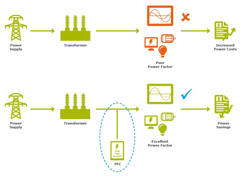
What is Power Factor Correction?
Reducing the amount of reactive power in a system and increasing the amount of active power is known as power factor correction. Capacitor banks or synchronous motors are used for power factor correction and improvement. Various industries use capacitor banks to correct the power factor.
What are the disadvantages of a low power factor in a system?
If the power factor is low, several problems occur in the system:
- Increased line losses.
- Larger size cables are required.
- Decreased efficiency of the power system.
- Increased initial cost, leading to a higher per-unit cost.
What is Economic Power Factor and its formula?
The power factor value that results in the highest annual savings when improved is called the economic power factor.
What is the power factor at resonance in an AC series circuit?
At resonance in an AC series circuit, the power factor is 1 or unity. In resonance, the inductive reactance and capacitive reactance are equal (XL = XC). Thus, the total impedance Z = R + j(XL – XC) = R. Therefore, the power factor, cosθ = R/Z = R/R = 1. Also, θ = cos⁻¹(1) = 0°. This indicates that the phase angle between current and voltage is zero at resonance
