

An electrical Transformer is crucial for transferring electrical energy between circuits. This article explains how transformers work, their different types, and their efficiency.
Table of Contents
What is a Transformer?
A transformer is a stationary electrical device that transfers electrical energy from one circuit to another without changing the frequency.
Study smarter with VoltageLab
Built for electricians, apprentices, and electrical engineers who want faster practice and better exam prep.
⭐️ Join thousands of electricians upgrading their skills
How Does a Transformer Work and Why Is It Used?
How it Works: A transformer primarily operates based on mutual induction. Now, you might wonder what mutual induction is.
“When a current change in one circuit induces an electromotive force (EMF) in another circuit that is magnetically linked, this process is called mutual induction.”
When an electrical supply is given to the primary coil, a magnetic field is generated around it, which is then collected by the secondary coil.
This creates mutual induction between the primary and secondary coils, causing electricity to flow in the secondary coil.
In other words,
A transformer has no moving parts, meaning it is a completely stationary device. Its construction is very simple, such as two or more insulated copper wires wound around an insulated steel or iron core (laminated steel/Iron core).
We know that a transformer has two windings, primary and secondary. When voltage is applied to the primary winding, a magnetic field is created, and the magnetic flux passes through the iron core to the secondary winding, creating a magnetic field there as well.
As a result, voltage is induced in the secondary coil. The amount of electricity flowing in the secondary side compared to the primary side depends on the number of turns in the primary and secondary coils, which is known as the transformation ratio.
Why It Is Used: Transformers are generally used to step up or step down voltage. For example, consider a substation with a voltage of 11 kV, but the consumer level requires 400/220 volts.
In this case, a transformer is used to step down the 11kV voltage to 400/220 volts.
Different Parts of a Transformer:
A transformer mainly consists of two parts:
- Primary Coil: The side of the transformer where power supply is provided is called the primary coil.
- Secondary Coil: The side of the transformer where the output is collected is called the secondary side.
In addition, a three-phase transformer has other parts, which are discussed below:
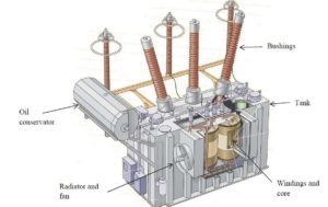
- Core: The steel frame around which the windings are wrapped is called the core. Using a steel core allows the magnetic flux generated on the primary side to easily link with the secondary.
- Winding: A transformer’s winding can have two or more coils. These coils are usually made with super enamel copper wire.
- Insulation: To insulate the core from the coil, non-conductive paper (insulating paper) is used on the core. The coil itself is insulated between the turns with a super enamel coating.
- Tank: The tank of a transformer contains oil in which the windings and core are immersed. The tank is sealed with a weatherproof gasket. The core is fixed to the bottom of the tank.
- Transformer Oil: The oil used inside the tank is called transformer oil. It is primarily used for insulation and to keep the windings cool.
- Conservator: The volume of the transformer oil changes with its temperature. A drum is used on top of the tank to accommodate these changes. This drum is called the conservator.
- Breather: As the volume of transformer oil changes, air enters and exits the tank. To keep this air dry and free of moisture, a glass container is used, called a breather.
- Bushing: The transformer windings’ terminals are brought outside the tank through bushings. The primary coil is connected to the AC source, and the secondary coil is connected to the load via these bushings.
- Earth Point: To protect the transformer from various hazards, it has two earth points. These earth points are connected to the ground.
Types of Transformers
Based on Operation
- Step-Up Transformer: A transformer that provides a higher output voltage compared to the input voltage is called a step-up transformer. Example: Step-up transformers are used in IPS, UPS, etc.
- Step-Down Transformer: A transformer that provides a lower output voltage compared to the input voltage is called a step-down transformer. Example: Step-down transformers are used in household electronic devices, such as televisions, DVD players, charger lights, etc.
Based on Usage
- Power Transformer: This type of transformer changes both current and voltage at the output. Typically, this type of transformer steps up or steps down AC at the input. Examples: Auto-transformers, toroidal transformers, variable transformers, etc.
- Distribution Transformer: Distribution transformers, or service transformers, are used to distribute power to consumers. Voltage is stepped down according to demand and distributed at the consumer level.
- Auto Transformer: An auto-transformer is a type of transformer with only one winding, part of which is shared between the primary and secondary coils, making them electrically and magnetically connected.
- Instrument Transformer: An instrument transformer is a highly accurate electrical device used to change the level of voltage and current separately.
Instrument transformers can be further categorized into:
- Current Transformer (CT): This transformer reduces high current to a lower range for measurement using low-range meters.
- Potential Transformer (PT): This transformer reduces high voltage to a lower range for measurement using low-range meters.
Based on Frequency
- Audio Frequency Transformer: Audio frequency transformers are typically used in audio amplifier circuits ranging from 20Hz to 20,000Hz.
- Radio Frequency Transformer: These transformers are used to transfer radio frequency energy from one circuit to another.
Based on Number of Phases
- Single-Phase Transformer
- Polyphase Transformer
Based on Installation
- Indoor Type Transformer
- Outdoor Type Transformer
- Underground Transformer
- Pole Mounted Transformer
Transformer Losses
- Iron or Core Losses
- Copper or Resistance Losses
- Stray Losses
- Dielectric Losses
Iron or copper losses can be further categorized into:
- Eddy Current Losses
- Hysteresis Losses
Transformer Efficiency
Transformer efficiency refers to the ratio of output power to input power. There is no machine in the world with 100% efficiency, but transformers can achieve efficiency ranging from 90% to 99% of the input power.
Therefore, it can be understood that transformers have the highest efficiency with minimal power loss.
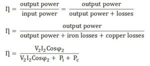
Where,
- V2 – Secondary terminal voltage
- I2 – Full load secondary current
- Cosϕ2 – Power factor of the load
- Pi – Iron losses = Hysteresis losses + Eddy current losses
- Pc – Full load copper losses = I22Res
Practice more with electrical quizzes
NEC · BS7671 · AS/NZS · CEC · DIN VDE
