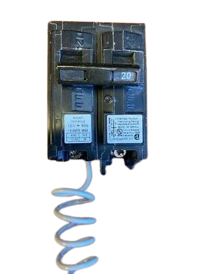
Have you heard about the shunt trip circuit breaker? How will we draw the shunt trip breaker wiring diagram? We are acquainted with a circuit breaker that protects our power system from unwanted faults such as a short circuit.

Electricity is more ferocious than the leopard. A few days back, a leopard fell in death due to the flow of electricity. So, it’s very essential to develop a protection system with a view to avoiding an unwanted accident. A shunt trip circuit breaker is a vital solution in these circumstances. Let’s know the function & shunt trip breaker wiring diagram in a simple manner.
What is shunt trip breaker?
This breaker is assembled with two basic parts:
- Shunt trip accessories
- Main circuit breaker part
Shunt trip accessories are attached to the main circuit breaker to protect the electrical system from any kind of undesired circumstances.
So, we can say that A shunt trip is an essential part of a circuit breaker that mechanically trips the breaker when power is applied to the shunt trip terminals. Now a question may arise, how do shunt trips consume power?
How Do Shunt Trip Breakers Consume Power?
Shunt trip consumes power from an external power source. It doesn’t consume power from the circuit breaker cascaded with it.
How does Shunt Coil work?

A shunt coil is used in the shunt trip breaker. It is used before the arrival of the relay. This shunt coil contains an electromagnet that is energized by an external power source and produces a magnetic field. There is a moveable bar that is attached to a spring for physical movement.
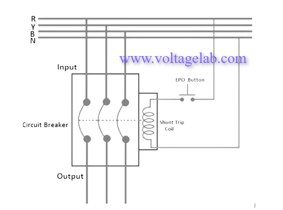
The shunt trip moveable bar hits the tripping point of the circuit breaker internally and the breaker becomes off. In the MCCB circuit breaker, the tripping point is named “push to the trip”. While switching on the breaker and pushing this button the breaker becomes switched off and trip due to pushing this button. The shunt trip coil rod pushes this point internally when the shunt coil is operated. This will be more clear to u when I will discuss the shunt trip breaker wiring diagram.
Shunt Trip Breaker Wiring Diagram and Connection Proceedure

Please look at the above shunt trip breaker wiring diagram. A mentioning fact is that here the tripping coil in the MCCB is rated for 230V single-phase supply. Let’s discuss the connection procedure:
- At first we have to connect the neutral wire of the power supply to anyone terminal of the shunt trip coil. If its terminals are identified, then connect to the neutral terminal.
- Then we have to connect anyone terminal of the EPO (Emergency Push Off) button to any one phase of the power supply from the output of the MCCB.
- Finally, the rest terminal of the shunt trip coil should be connected with another terminal of EPO button. Connect another terminal of the EPO button.
- If the operating volt of the shunt coil is 220 volt, then we require to supply 220 volts to the shunt coil to operate or trip the breaker in a faulty time. So, our neutral will be connected directly to the shunt tripping coil, and the live line will be connected to the coil on another side through the EPO push-button switch normally open contacts.
How Shunt Trip Breaker Differs From Regular Circuit Breaker?
- Ground fault breakers monitor the current on the neutral wire. On the other hand, shunt trip breakers can be tripped after energizing the shunt coil.
- Regular breakers utilize a relay for tripping purposes but shunt trip coil breakers use a shunt coil in this regard.
- GFCI (Ground Fault Circuit Interrupter) can’t be connected to a control circuit but shunt trip breaker is connected to control circuit.
Read More Articles


