

A half wave rectifier is an essential component in the field of electronics, designed to convert alternating current (AC) into pulsating direct current (DC). This process involves rectifying only one half of the AC waveform, resulting in a DC output that corresponds to the positive or negative half-cycle of the input signal. Half wave rectifiers are widely used in various applications due to their simplicity and ease of implementation. This article explores the working principles, components, and operation of half wave rectifiers, providing a comprehensive understanding of how they function in electronic circuits.
Half Wave Rectifier
A half wave rectifier means it will rectify only half of the waveform. When a full cycle is provided to the input of a half wave rectifier, the output will yield half a DC cycle, meaning it will rectify only the half cycle. This is essentially the function of a half wave rectifier.
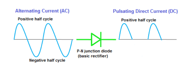
A half wave rectifier is a type of rectifier that converts the positive half cycle of the input into pulsating DC at the output. The simplest rectifier circuit is the half wave rectifier circuit.
Components Required to Build a Half Wave Rectifier:
- AC Source
- Transformer
- Diode
- Resistor
AC Source
An AC source typically supplies alternating current to the circuit. Alternating current is represented by a sinusoidal waveform.
Transformer
A transformer is a device that either increases or decreases AC voltage. A step-down transformer reduces the AC voltage, while a step-up transformer increases the AC voltage.
In a half wave rectifier, a step-down transformer is typically used because the diode requires very low voltage. In some cases, a step-up transformer may also be used.
In a step-down transformer, the number of turns in the primary winding is greater than in the secondary winding.
Diode
A diode is a two-terminal device that allows current to flow in one direction and blocks it in the opposite direction.
Resistor
A resistor is an electronic component that opposes the flow of current.
Half Wave Rectifier Operation
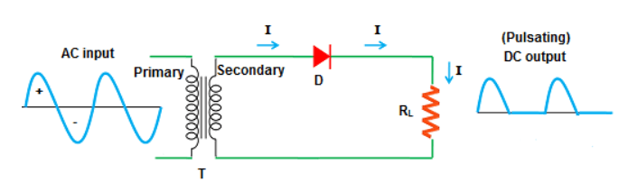
Here,
I = Current
D = Diode
RL = Load Resistor
T = Transformer
+ = Positive Half Cycle
– = Negative Half Cycle
In the case of positive and negative half cycles:
When a 220V supply is provided at the input, the step-down transformer used in the circuit reduces the voltage at the output. The low voltage in the secondary winding of the transformer flows directly to the diode.
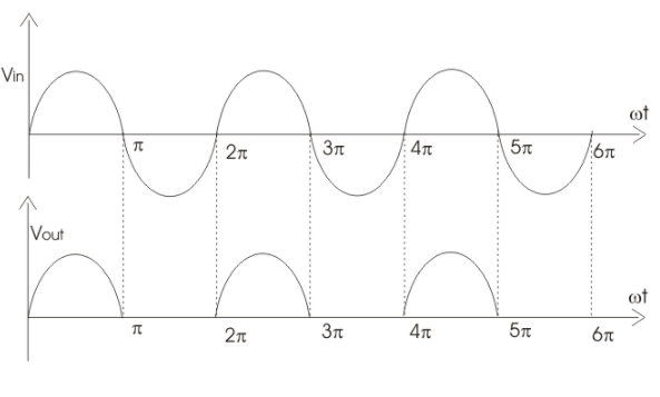
During the positive half cycle, the diode is forward biased and allows current to pass. During the negative half cycle, the diode is reverse biased and blocks the current flow. In short, the diode allows the positive half cycle to pass and blocks the negative half cycle.
The output waveform is shown below.
FAQs Related to Half Wave Rectifiers
Peak Inverse Voltage (PIV): The maximum reverse voltage that a diode can withstand is called Peak Inverse Voltage.
Average Value: The average of the instantaneous values of a variable quantity during a half cycle is called the average value.
Average Value = 2 / π * Maximum Value
Ripple Factor: The ratio of the RMS value of the AC component to the DC component of the pulsating DC obtained at the output of a rectifier is called the Ripple Factor.
That is, Ripple Factor = RMS Value of AC Component / DC Component Value.
The Ripple Factor value for a half wave rectifier is 1.21.
Form Factor: The ratio of the RMS value to the average value of a sine wave is called the Form Factor. In the case of a half wave rectifier, it is equal to 1.57. It is denoted by Kf.
Kf = RMS Value / Average Value
Peak Factor: The ratio of the maximum value to the RMS value of a waveform is called the Peak Factor or Amplitude Factor. It is denoted by Ka.
Ka = Maximum Value / RMS Value
