

The Full Wave Rectifier & Bridge Rectifier are crucial components in converting alternating current (AC) into direct current (DC) for various electronic applications. These rectifiers process both the positive and negative cycles of the AC input, providing a more efficient and consistent DC output compared to half wave rectifiers. In this article, we will delve into the different types of full wave rectifiers, including the Center Tap and Bridge Rectifiers, and explore their components and operational principles.
Full Wave Rectifier
A full wave rectifier means it will rectify the entire waveform. In other words, when a full cycle is given as input to the full wave rectifier, current will flow at the output for both the positive and negative cycles.
This operation is primarily achieved with the help of two diodes. One diode works for the positive half-cycle of the input voltage, while the other diode works for the negative half-cycle. This means the current will always flow in the same direction through the load.
Two types of circuits are commonly used for full wave rectification:

- Center Tap Full Wave Rectifier
- Full Wave Bridge Rectifier
Center Tap Full Wave Rectifier
The components required to build a center tap full wave rectifier are:
- AC Supply
- Transformer
- Two Diodes
- Load Resistor
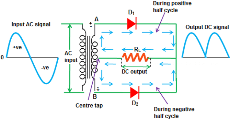
The above figure shows the input AC signal and the output DC signal. The transformer’s secondary winding is center-tapped and connected to the load resistor or output, which is why it is called a center tap full wave rectifier. The figure shows two diodes, D1 & D2.
Here,
I = Current

D = Diode
RL = Load Resistor
T = Transformer
+ = Positive Half Cycle
– = Negative Half Cycle
A & B = Two Terminals
Operation:
During the positive half cycle, the A terminal of the secondary winding will be positive, and the B terminal will be negative. In this case, the diode at terminal A will be forward biased (it will conduct according to the properties of the diode), and the diode at terminal B will be reverse biased (no current will flow).
In other words, when diode D1 is forward biased or in conduction, diode D2 will be reverse biased. Under such conditions, current will flow through diode D1 and the load resistor RL, as shown in the circuit with the arrow –>.
During the negative half cycle, the B terminal of the secondary winding will be positive, and the A terminal will be negative. In this case, the diode at terminal B (D2) will be forward biased, and the diode at terminal A (D1) will be reverse biased. In this state, current will flow through D2, while D1 will be reverse biased.
Full Wave Bridge Rectifier
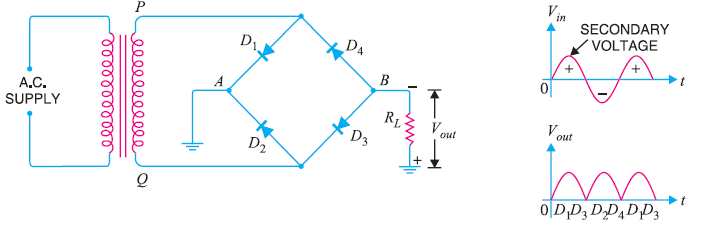
In the above figure, you can see that a full wave bridge rectifier uses four diodes, a transformer, and a load resistor. The four diodes D1, D2, D3 & D4 are typically connected in such a way that they resemble a bridge. The load resistor is connected to terminals A and B.
Operation:
During the positive half cycle, the P terminal of the secondary winding will be positive, and the Q terminal will be negative. As a result, diodes D1 & D3 will be forward biased, while diodes D2 & D4 will be reverse biased. Consequently, diodes D1 & D3 will conduct. These two diodes D1 & D3 will be connected in series with the load resistor. The current will flow from A to B.
During the negative half cycle, the P terminal of the secondary winding will be negative, and the Q terminal will be positive. As a result, diodes D2 & D4 will be forward biased, while diodes D1 & D3 will be reverse biased. Consequently, diodes D2 & D4 will conduct, and the current will once again flow from A to B.
What is a Full-Wave Rectifier?
A Full-Wave Rectifier is a type of rectifier that converts the entire waveform of alternating current (AC) into direct current (DC), allowing current to flow through the load during both the positive and negative cycles of the AC input.
What is the Principle of a Rectifier?
The principle of a rectifier is to convert AC (which periodically reverses direction) into DC (which flows in a single direction). This is achieved by using components like diodes, which allow current to pass only in one direction, effectively blocking one half of the AC cycle.
What are the Advantages of a Full-Wave Rectifier?
The advantages of a full-wave rectifier include higher efficiency in converting AC to DC, smoother output voltage, and reduced ripple compared to a half-wave rectifier. It also makes better use of the AC input, as it rectifies both halves of the waveform.
What is a Full-Wave Bridge Rectifier?
A Full-Wave Bridge Rectifier is a type of full-wave rectifier that uses four diodes arranged in a bridge configuration to convert AC into DC. It efficiently rectifies both the positive and negative halves of the AC input without requiring a center-tap transformer.
What is the Working Principle of a Bridge Rectifier?
The working principle of a bridge rectifier involves using four diodes to direct the current during both halves of the AC cycle. During the positive half-cycle, two diodes conduct to allow current flow, and during the negative half-cycle, the other two diodes conduct, ensuring that the current flows in the same direction through the load during both halves.
