
Electrical Transformer testing is a crucial aspect of ensuring the reliability, efficiency, and safety of power systems. These tests validate the operational integrity of transformers, checking everything from electrical performance to insulation strength. Adhering to standardized testing procedures not only prevents potential failures but also extends the lifespan of these vital devices. In this guide, we explore the key transformer testing standards, methods, and equipment, offering insight into best practices for maintaining transformer health in both industrial and utility settings.
Transformers play a major role in the power system. Transformer testing is an important topic because we know that a transformer is a static device where the voltage of an AC supply is increased or decreased with respect to the current. Most of the time, the transformer remains active except during maintenance or power outages.
Transformer testing is performed to determine whether the transformer is operating correctly.
Types of Transformer Tests
Types of tests performed in the factory:

- Type Test
- Routine Test
- Special Test
Types of tests performed on-site:
- Pre-Commissioning Tests
- Periodic/Condition Monitoring Tests
- Emergency Tests
Type Test:
This is a type of transformer test through which the electrical and mechanical parameters are verified to ensure their quality. Type tests include:
- Transformer Ratio Test
- Measurement of Transformer Winding Resistance
- Transformer Vector Group Test
- Measurement of Impedance Voltage/Short Circuit Impedance and Load Loss
- Measurement of No Load Loss and Current
- Measurement of Insulation Resistance
- Dielectric Test of Transformer
- Temperature Rise Test
- Load Tap Changer Test
- Vacuum Test of the Tank and Radiator
Routine Test:
- Transformer Winding Resistance Test
- Phase-to-Phase Winding Resistance Test of HT and LT sides of the transformer
- Transformer Ratio Test
- Transformer Vector Group Test
- Measurement of Impedance Voltage/Short Circuit Impedance and Load Loss
- Measurement of No Load Loss and Current
- Measurement of Insulation Resistance
- Dielectric Test of Transformer
- Load Tap Changer Test
- Oil Pressure Test
In Routine Tests, all tests are conducted except for the temperature rise and vacuum tests.
Special Test:
- Dielectric Test of Transformer
- Zero Sequence Impedance Test of Three-Phase Transformer
- Short Circuit Test
- Measurement of Noise Level
- Harmonic Measurement in No-Load Current
- Measurement of Power Taken by Fan and Oil Pump
- Test of Buchholz Relay, Temperature Indicator, Pressure Relief Devices, and Oil Conservator System
Transformer Ratio Test
The Transformer Ratio Test is a type of routine test conducted to verify whether the voltage ratio of the LT side relative to the HT side is correct. The main purpose of this test is to ensure that the ratio designed for the HT and LT windings matches the specified design.

In Bangladesh, it is common for the input voltage to vary on the HT side, so several tap positions are provided in the HT winding. The voltage ratio is measured at each tap position in relation to the HT side.
The voltage ratio of a 11000/415V three-phase transformer is approximately 26.506.
To conduct the ratio test on a three-phase transformer, 415V is supplied to the HT side, and the ratio is checked on the LT side. This test is conducted separately for each tap position.
Vector Group and Polarity Test
A vector group test is conducted on three-phase transformers. There are different groups of transformers depending on the connection diagram of the high tension and low tension windings.
Observe the following diagram:
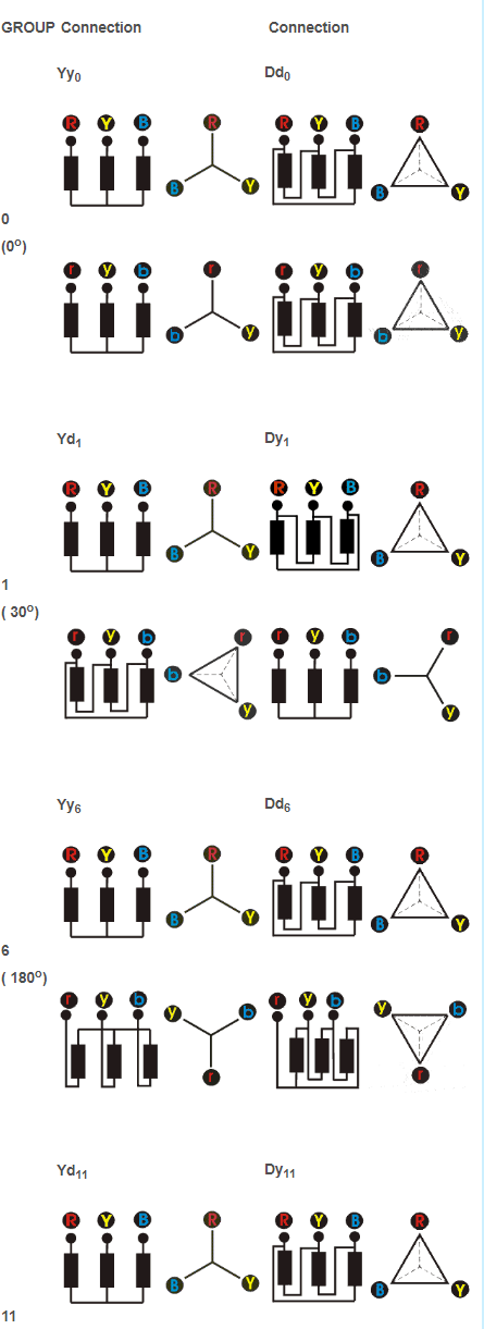
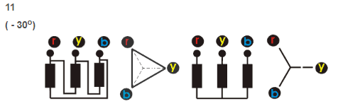
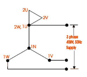
For a YNd11 transformer:
- Connect the neutral point of the star winding to the ground.
- Connect 1U to the HT side and 2W to the LT side.
- Supply 415V to the HT terminal.
- Measure the voltage between terminals 2U-1N, 2V-1N, and 2W-1N, i.e., the voltage between the HT and LT.
- Measure the voltage between terminals 2V-1V, 2W-1W, and 2V-1W.
For the YNd11 transformer, we will get:
2U-1N > 2V-1N > 2W-1N
2V-1W > 2V-1V or 2W-1W
Other groups are tested similarly.
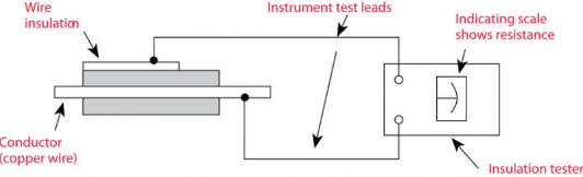
Transformer Dielectric Test
The dielectric test is a type of test that measures the insulation level of a transformer.
There is no direct electrical connection between the high tension and low tension windings, so there must be resistance between them. We know that the resistance depends on the insulation of the windings and the dryness of the insulating elements. The dielectric tester is also called a Megger meter.
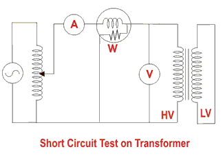
Transformer Full Load Loss / Short Circuit / Copper Loss Test
This test requires the low voltage side to be shorted. The short circuit test is performed for the following reasons:
- To determine copper loss
- To determine equivalent resistance, reactance, and impedance
- To determine efficiency and voltage regulation
In the transformer’s low-tension side, all terminals are shorted, and the rated current is supplied to the high-tension side, and the load loss is measured using a wattmeter. The voltage obtained at the output of the high-tension side when the rated current is supplied is called the impedance voltage.
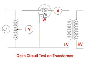
Transformer Open Circuit / No Load / Core Loss Test
During this transformer test, the high side is kept open, and the low voltage side is connected to the equipment. The open circuit test is performed for the following reasons:
- To determine no-load current
- To determine core loss
During this test, the rated voltage is supplied.
The connection diagram for the open circuit test is provided below. A voltmeter, wattmeter, and ammeter are connected to the low voltage side. In this test, the rated voltage is supplied to the transformer’s LT side, and the current it draws in this condition is called no-load current. The rated voltage is induced in the HT transformer, and the no-load loss or core loss refers to the loss incurred as a result of the small current drawn by the low voltage side due to the supplied rated voltage.
Transformer High Voltage Test
The high voltage test is a transformer test used to measure the dielectric strength of the dielectric materials inside the transformer. We know that transformer oil is used to increase dielectric strength.
Both the high-tension and low-tension sides are shorted separately, and the high voltage phase is applied to the high-tension terminal while grounding the low-tension terminal and the transformer body. Then, about 2.5 times the high-tension rated voltage is applied for approximately one minute to conduct the test.
The breakdown voltage of transformer oil in a specific phase-to-ground distance is quite high, typically ranging from 40 to 70 kV.
In the case of a 11000/415 step-down transformer, the high-tension side is given 11000*2.5 = 27500 or 28000 volts.
However, sometimes less than 2.5 times is applied. For transformers in a 33 kV line, 70000 volts is applied to the high-tension side.
1. What are the tests for transformers?
Transformers undergo various tests to ensure their operational efficiency and safety. These tests include Type Tests (such as Ratio Test and Winding Resistance Test), Routine Tests, and Special Tests (such as Dielectric and Short Circuit Tests). Each test verifies different electrical and mechanical parameters.
2. What is the test for a 3-phase transformer?
For a 3-phase transformer, common tests include the Transformer Ratio Test, Winding Resistance Test, Vector Group Test, and Short Circuit Test. These tests ensure the proper functioning of the high and low voltage windings and overall efficiency of the transformer.
3. What are the transformer testing methods?
Transformer testing methods are classified into two categories: factory-based and on-site tests. Factory tests include Type, Routine, and Special tests, while on-site tests cover Pre-Commissioning, Periodic/Condition Monitoring, and Emergency tests.
4. What is a transformer testing kit?
A transformer testing kit is a specialized toolset used to conduct various diagnostic tests on transformers. It typically includes devices like insulation testers, winding resistance meters, ratio meters, and dielectric testers.
5. What transformer testing equipment is used?
Transformer testing equipment includes devices like insulation resistance testers (Megger), transformer turns ratio testers, winding resistance meters, dielectric strength testers, and high-voltage testing equipment.
6. How many types of transformer testing are there?
There are primarily three types of transformer tests: Type Tests (to verify design specifications), Routine Tests (to ensure consistent performance), and Special Tests (for unique performance parameters). Additionally, on-site tests like Pre-Commissioning and Periodic Tests are also performed.
