Electrical Cable is essential components in both electrical and data communication systems, serving as the conductors through which current or data flows. They come in various types, each designed for specific purposes and performance standards. Whether it’s coaxial cables for TV connections or fiber optic cables for high-speed data transmission, understanding the properties, types, and sizing of cables is crucial for safe and efficient electrical installations. In this guide, we’ll explore different cable types, explain electrical markings, and walk through methods for determining the correct cable size for your application.
What is a Cable?
We understand a cable to be an electric conductor wire through which current flows. In data communication, the cable is an important medium.
Types of Electrical Cables and Brief Descriptions
Cables can be categorized as follows:
- Coaxial Cable.
- Two-State Pair Cable.
- Fiber Optical Cable.
- Unshielded Twisted Cable.
- Flexible Cable.
- Vulcanized Cable.
- Polyvinyl Cable.
There are many more types of cables.
- Coaxial Cable: We often see a coaxial cable in use for connecting TVs to satellite dishes in households. Additionally, TV connections with antennas in homes are made via coaxial cables. Typically, this type of cable is used in local area networks. These cables are primarily copper-based. They come in various types like 50 ohm (RG-8, RG-58), 75 ohm (RG-59), and 93 ohm (RG-62). This type of cable is relatively inexpensive.
- Two-State Pair Cable: This type of cable is very common and inexpensive. It consists of two insulated copper wires twisted together. The term “twisted” means twisted or coiled. Twisted pair cables are used in telephone systems.
- Fiber Optical Cable: This cable transmits data via light. It is very thin and made of fine glass or plastic strands. Data can be transmitted over long distances easily with this cable. However, it is more expensive than others.
Meaning of Different Letters or Symbols on Electrical Cables
- VDE – German Electrical Engineering Association
- N – German Electrical Engineering Association
- B – According to British standards
- I – According to BS 2004: 1961
- Y – PVC-based insulation
- A – Single core wire
- M – Wire with a solid sheath
- F – Flat cable
- R – Galvanized steel flat wire with a metal coating.
- Gb – Twisted galvanized steel tape.
- re – Single conductor round wire.
- Rm n. – Multiple conductor round wire.
- Sm – Multiple strand flat wire (telephone).
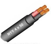
BDS: 900/901 BS: 6004:1984
- BYA PVC – Single core insulated cable but without a solid sheath
- BYFY – Single core and one conductor insulated cable but without a solid sheath
- BYFY PVC – Insulated and PVC-sheathed flat cable
- NYA PVC – Uninsulated single core wire
- NYIFY PVC – Insulated and PVC-sheathed flat wire
- NYMT PVC – Insulated, PVC-sheathed flat wire strengthened with steel wire
VDE 0271
BDS: 900:1979, BS: 2004:1961
- IYAL – PVC insulated but without a solid sheath
- IYYL – Single core insulated and PVC-sheathed wire
- IYFY – Insulated and PVC-sheathed flat wire
- NYY – PVC-insulated and PVC-sheathed cable
How to Determine Wire Size from Markings or Without Markings?
Working with cables without knowing their size can be very dangerous as the cable might not be suitable for the job. This can lead to disruptions in electrical work.
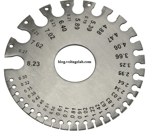
We know that wire size is expressed through Standard Wire Gauge (SWG). We often see gauges like 3/22″, 7/22″, etc. for wires.
- A question: What does 1*3*0.29 mean? It means a single core with three strands, and each strand has a diameter of 0.029. See the image below:

- Similarly, 1*1/1.80 means a single core with one strand, and the strand diameter is 1.80 mm.
- In homes, wire sizes are usually 1, 2.5, and 4 square millimeters, and the standard wire gauge numbers are 3/22, 3/20, 7/18, 7/22, etc. Below is an image of a Standard Wire Gauge. This gauge helps determine wire size.
- Sometimes wires are marked with RM, SM, or RE. RM means multi-strand round conductor wire. SM means multi-strand sector-shaped wire. RE means single solid conductor round wire.
How Does an Ideal Engineer Determine Wire Size for Households?
There are many opinions on how to determine wire size. Some think consulting the manufacturer’s catalog is sufficient, while others find the selection process complicated. In this article, I will try to explain it as simply as possible.
Now we will learn how to determine wire size for low-voltage household applications. This can be done in a few steps.
Calculating Load Current
First, we need to calculate the load current. I will try to show you simply how to calculate load current. Let’s consider wiring for a residential building.
Assume the total power load for the building is 5300 watts, which is the sum of all individual loads. We also know that the load in homes gradually increases as various appliances are used for different needs. Therefore, it is important to consider future loads when selecting cables for homes.
The homeowner can provide insights into future load increases or the expansion plans of the building.
If for any reason it cannot be done, then an additional 20% load should be considered. Internationally, taking an additional 20% load is recognized.
So, let’s calculate:
Assume total power, P = 5300 watts. Voltage V = 220 volts. Power factor, cosθ = 0.9. Additional load = 20%
Total load power, P = {5300 + (5300*20/100)} = 6360 watts.
Total current, I = (P/Vcosθ) = {6360/(220*0.9)} = 32.12A
The load current calculation is done, now let’s move to the next step.
Wiring method and cable determination
In households, we work with a single-phase line. So, we need to run two wires. How these wires are routed affects the rated amperage.
We know that when current flows through a cable, the cable heats up, and the more heat that is dissipated, the better, as the cable will cool down faster. The wire pulled over a perforated tray gets more air than the wire run inside the wall.
A wire pulled through a pipe outside the wall gets some air, but less than the wire pulled over the tray. This is the main impact of wiring.
Assume we will route the wire inside the wall. In this case, we need a cable of 6 square mm or 6 RM, whose amperage rating is 34 amperes.
You might ask, why a 6 square mm cable? A PDF book has been provided above, which gives the standard cable specifications for households, etc.
Ambient temperature determination
The conductive cable will try to dissipate heat through its surroundings. How fast the cable cools depends on the ambient temperature around it.
Since we have routed the cable inside the wall, which has a low thermal conductivity, heat will remain inside the wall, increasing the ambient temperature.
Assume the temperature is 40 degrees Celsius. Then, we need to apply a correction factor from 40 degrees Celsius, which is 0.85, as marked below.

Now, we’ll multiply 34 amperes by the correction factor (34*0.85) = 29 amperes. Our total load current was initially calculated as 32.12 amperes.
Therefore, this cable cannot carry such a high current. In this case, we need to select a cable from the datasheet one size larger.
Let’s assume we chose a 10 RM cable with a current carrying capacity of 46 amperes. Then, applying the correction factor: (46*0.87) = 40.02 amperes. (Since the chart gives 0.80 for 45 amperes, we assumed 0.87 for 46 amperes).
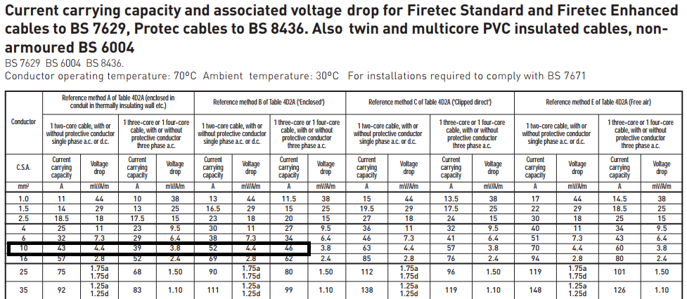
The total load current is 32.12 amperes, and the cable’s current carrying capacity is 40.02 amperes. So, this is perfect.
Special Note: According to the international cable current rating book, the current carrying capacity of a 10 RM cable is 46 amperes. In this case, BRB or BBS standards have not been considered. You can calculate according to BRB or BBS standards if you wish. However, do not use BRB or BBS standards in international calculations.
Voltage drop determination
Now, we will calculate the voltage drop inside the cable under full load current. To do this, we need to know “how much voltage drop will occur in a specific cable if one ampere of current flows through it for one meter”
Researchers have measured this for various RM cables and created a chart, which we’ve already seen in the PDF book. This value is expressed in mV/A/M.
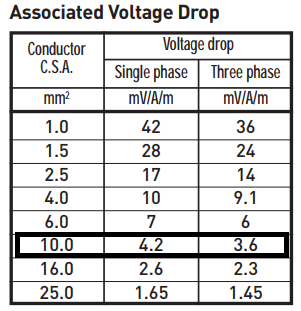
We previously calculated the total current as 32.12 amperes, and we are using a 10 RM cable, which shows a voltage drop of 4.2mV/A/M due to the single phase. Assume the total cable length is 30 meters.
So, the voltage drop will be = (32.12*0.0042*30) = 4.04712 volts
According to IEEE regulations, the voltage drop from the supply point to the installation should not exceed 2.5% of the supply voltage. Our supply voltage is 220 volts, and 2.5% of that is 5.5 volts, which is higher than 4.04712 volts.
This means that the cable is suitable for our wiring. If for any reason the voltage drop exceeds the permissible value, we will need to choose a larger cable size until the voltage drop falls within 2.5%.
What do RM, SM, SE, and RE mean for cables?
Many people wonder how to calculate RM for determining cable size. In reality, this is not an exact rule, although there are many formulas. Cable size determination depends on factors like voltage drop, distance, and load, which we have already discussed.
In many cases, cables are labeled RM, SM, SE, RE. These mainly refer to the unit of the cable. To determine cable size, we first need to understand these terms. Hopefully, the following diagram will help explain this clearly.
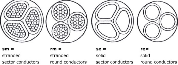
The RM in the diagram above indicates the cable’s construction and core alignment, with factors such as conductor material, insulation, sheath, and armor, all determining the cable’s performance. Depending on the installation type and location, selecting the correct RM cable is essential.
How Much Current Can Copper Wires Carry According to BRB/BBS Standards?
It is very important for those working in maintenance to know this information.
- 1.3 rm = 22A
- 2.5 rm = 30A
- 4rm = 39A
- 6rm = 50A
- 10rm = 69A
- 16rm = 94A
- 25rm =125A
- 35rm = 160A
- 50rm = 195A
- 70rm = 245A
- 95rm = 300A
- 120rm = 350A
- 150rm = 405A
- 185rm = 460A
- 240rm = 555A
- 300rm = 640A
- 400rm = 770A
- 500rm = 900A
- 630rm = 1030A
- 800rm = 1165A
- 1000rm = 1310A
FAQs:
1. What are the main types of cables used in electrical and data communication systems?
- The most common types of cables include Coaxial Cable, Two-State Pair Cable, Fiber Optical Cable, Unshielded Twisted Cable, Flexible Cable, Vulcanized Cable, and Polyvinyl Cable. Each serves specific purposes and has unique characteristics.
2. What is a coaxial cable and where is it used?
- Coaxial cables are primarily copper-based and are often used in household TV connections, satellite dishes, and local area networks (LANs). They come in various types like 50 ohm (RG-8, RG-58), 75 ohm (RG-59), and 93 ohm (RG-62), and are relatively inexpensive.
3. What does a fiber optic cable do?
- Fiber optic cables transmit data using light. These thin cables are made from fine glass or plastic strands and are capable of transmitting data over long distances efficiently. While they are more expensive, they provide high-speed data transmission.
4. What do the letters and symbols on electrical cables represent?
- Letters and symbols on cables, such as VDE, B, Y, and M, represent the cable’s standards and characteristics. For instance, VDE refers to the German Electrical Engineering Association, while Y represents PVC-based insulation.
Conclusion:
Choosing the right cable for any electrical or communication setup is vital for ensuring both safety and efficiency. From understanding the types of cables available to interpreting electrical markings and determining appropriate sizes, this knowledge is essential for both professionals and DIY enthusiasts. By considering factors such as load current, ambient temperature, and voltage drop, you can select the correct cable for your specific needs, ensuring long-lasting and reliable performance in your installations.


