We know that many elements are used for the transmission and distribution of Electric power from the power plants. So, today we will discuss what are the components of a substation?
Here is a list of substation components:
- Busbar
- Isolator
- ACR (Automatic Re-closer)
- PT (Potential Transformer)
- CT (Current Transformer)
- VCB (Vacuum Circuit Breaker)
- Transformer
- Insulator
- Lightning arrester
- PFI (Power Factor Improvement)
What are the components of a substation? / Substation Components
Busbar
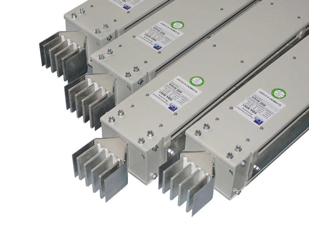
A busbar is a kind of copper or aluminum conductor rod, which collects Electricity from one or more circuit and distributes it. Many companies, mills, and factories take the connection from the busbar to their Electric wiring. A hole is made in the busbar by a drill machine and it wears a lug and gets connected by a nut. As people use the bridge for crossing rivers, Electricity uses the busbar to enter one system from another.
Isolator
Isolate means disconnection. An isolator is a manual mechanical switch, which disconnects any part of the Electrical machine if needed. Generally, an isolator operates in a no-load connection or in offline. There is no special system for extinguishing arch. Many devices in Electrical substations like isolators are used for disconnecting the transformer from the line because of no-load or low-load conditions.

Automatic Re-Closer
In an Electrical distribution system, an auto re-closer is a special kind of circuit breaker. If any fault occurs in the system, it opens the entire circuit and closes it after a fixed time (in seconds/set time). If a fault occurs frequently, the re-closer will open the circuit frequently and then close it after a time. There must be an auto re-closer in every substation.
An engineer can set how many times the circuit will open and close if any fault occurs.

Example: Suppose there is a fault in the system. And the re-closer opened the circuit and then closed it after a time. But the breaker can still detect the fault and it opened and closed the circuit again. An engineer can set how many times the circuit will open and close. If there is no fault, the re-closer will open the circuit. In this case, if only a circuit breaker is used then it will just open the circuit but can’t close it automatically.
PT ( Potential Transformer )
We know that it is not easy to measure high voltage in transmission and distribution lines. An instrument transformer (Potential Transformer) is used for measuring high voltage.
A current transformer is used for measuring current, and a potential or voltage transformer is used for measuring the voltage of the transmission and distribution line.
The potential transformer is also called a voltage transformer. It is a type of transformer which converts a high amount of voltage into a low range. It is used for measuring the high amount of voltage of the circuit by a low range meter.

CT ( Current Transformer )
A current transformer is used for measuring alternating current. A current transformer is mainly used for measuring high currents. We know that there is a high amount of current in a high-power line. in this case general ammeter or multimeter cant measure the current. That’s why a current transformer is used.

VCB ( Vacuum Circuit Breaker)
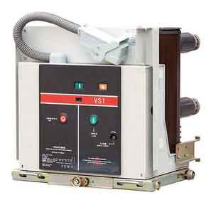
A vacuum circuit breaker is a kind of circuit breaker which works as a fire extinguisher through blank space and completes the braking operation. This circuit breaker is used between 11 to 33 kV.
The reasons behind using a vacuum circuit breaker
- It looks like a packet from the outside, dependable and long-lasting.
- No risk of fire.
- No chance of producing gas before or after braking operation.
- It can break any fault current.
- There is less need for maintenance.
Transformer
A transformer is a still electrical device. It helps current to flow from one circuit to another, without changing the frequency.

Insulator
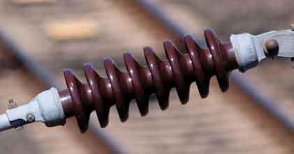
Normally insulator is placed between the conductor and support and connects both of them. Current can’t flow in insulator and so current can’t go to pillar from transmission line.
Lightning arrester
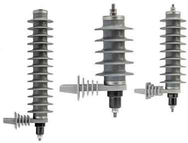
Lightning means thunder and arrester means to capture. It means if thunder hits the transmission line there is a high chance of getting high voltage in line and causing harm. That’s why a lightning arrester is used for discharging extra voltage on the ground.
PFI (Power Factor Improvement)
If we say generally, the cosine value of the angle between current and voltage is the power factor. The power factor indicates the percentage of electricity we need. The power factor’s value is 0-1.
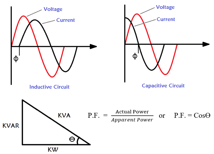
The power factor is indicated by cosθ and θ is the angle between voltage and current. If the angle increases, the power factor decreases. And when the angle decreases, the cosine value or power factor increases.
That was all for today’s article what are the components of a substation?
Hope now you can understand what are the components of a substation?
If you have any questions on what are the components of a substation, you can ask in the comment section.
You can also read: Discussion about Composite Insulating Cross-Arms


