
Logic gate is a fundamental building block of digital circuits. These electronic circuits take one or more input signals and produce a single output based on a specific logical function. The most basic logic gates—AND, OR, and NOT—form the core of complex digital systems, enabling everything from simple calculations to advanced computing tasks. Understanding how these gates work is essential for anyone interested in electronics, computer science, or digital logic design.
A logic gate is a type of electronic circuit that takes one or more inputs and provides a single output.
Basic Logic Gate (AND, OR, NOT) Types, Function & Truth Tables
This article will cover the following topics:
Study smarter with ElectricPal
Built for electricians, apprentices, and electrical engineer who want faster practice and better exam prep.
Available for Android and iPhone.
- Introduction to Logic Gates
- Types of Logic Gates
- Concept of Basic Logic Gates
Introduction to Logic Gates
The term “Logic Gate” is derived from English. The word “logic” refers to reasoning, meaning it operates based on logical concepts. We know that computers understand only the binary numbers 0 and 1. Similarly, logic gates are designed to interpret these two numbers. To fully comprehend Boolean algebra and De Morgan’s Theorem, logic gates are essential. Through logic gates, we can understand the relationship between inputs and outputs.
Types of Logic Gates
Logic gates can be categorized as follows:

There are three basic types of logic gates:
- AND Gate
- OR Gate
- NOT Gate
Below are images of different gates with their symbols and truth tables. The gate inputs are labeled as A and B, with the output as Q. The truth table logically calculates the states of inputs and outputs.
AND Gate
- It will have two or more inputs and a single output.
- The AND gate functions as multiplication; the output will be 1 only if all inputs are 1.
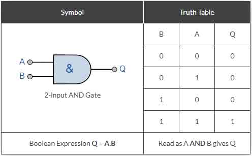
Assume there are two inputs, A and B. If both inputs are 1, the output will be 1. For example, if A = 0 and B = 1, or A = 1 and B = 0, the output will be 0. However, if A = 1 and B = 1, the output will be 1, as shown in the truth table below.
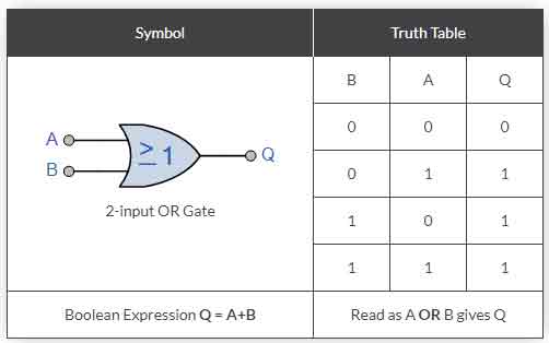
OR Gate
- It will have two or more inputs and a single output.
- The OR gate functions like addition; if any input is 1, the output will be 1; otherwise, the output will be 0.
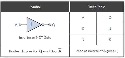
NOT Gate
The NOT gate will have a single input and a single output. The output will be the opposite of the input; for example, if the input is 0, the output will be 1.
What is an AND gate, and how does it function?
An AND gate is a basic logic gate that outputs a high signal (1) only when all of its inputs are high (1). If any input is low (0), the output will be low (0). It performs a logical multiplication of inputs.
How does an OR gate work, and what is its purpose?
An OR gate outputs a high signal (1) if at least one of its inputs is high (1). It functions like a logical addition where the output is high if any input is high, and only low (0) if all inputs are low.
What does a NOT gate do, and how is it used in digital circuits?
A NOT gate, also known as an inverter, outputs the opposite of its input. If the input is high (1), the output is low (0), and vice versa. It is used to invert the signal and is essential for creating various logical functions.
How can I combine AND, OR, and NOT gates to create complex logic circuits?
By combining these basic gates, you can create complex logic circuits that perform a wide range of functions. For example, using AND and OR gates together can form a NAND gate, while NOT gates can be used to invert inputs or outputs of other gates, enabling the creation of more sophisticated logic operations.
What are the practical applications of AND, OR, and NOT gates in real-world electronics?
These gates are used in various applications, such as digital arithmetic operations, memory storage, data processing, and control systems. They are integral to the design of processors, memory chips, and other digital devices, forming the foundation of modern electronic systems.
Ready to pass your exam?
Join thousands of electricians and apprentices using ElectricPal to study smarter and score higher.
Free to download · Available for Android and iPhone
