
Auto Transformer differs slightly in structure compared to regular transformers. Understanding these differences is essential. In this article, we will explore the structure and working principle of an auto-transformer, along with its advantages and disadvantages.
We all know more or less about transformers. However, structurally, an auto-transformer is a bit different. Therefore, it’s important to have a basic understanding of its differences. Now, I will discuss the structure and working principle of the auto-transformer.
Topics Covered in This Article About Auto-Transformers:
- Structure and Working Principle
- Advantages and Disadvantages
Auto Transformer Structure and Working Principle:
An auto transformer has only one coil. A part of it is common between both the primary and secondary sides. That is, the primary and secondary coils of an auto transformer are electrically and magnetically connected.
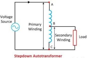
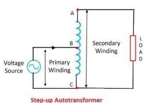
Still, it is called a transformer because its operation and behavior are similar to a two-winding transformer. In the diagram, the primary and secondary coils of this transformer are shown, where AC is the primary, and part of BC is the secondary, meaning the BC portion is common for both the primary and secondary (in the case of Step Down). On the other hand, AC is the secondary, and the BC portion is the primary and common for both (in the case of Step Up).
To get the required voltage in the secondary, a specific point is determined from the continuous coil, and the secondary voltage is taken from that point. In this transformer, the entire secondary power is not generated by transformer action alone; some power is transferred directly through the conductor.
The power transferred by transformer action is called transformed power, and the power transferred through the conductor is called conducted power. The KVA rating of this transformer depends only on VsIs. An auto transformer can be constructed in two ways.
First, the voltage is taken in the secondary by tapping from a suitable point on a single winding. Second, the required voltage in the secondary is taken by connecting two windings electrically and magnetically.

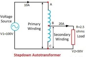
In the diagram, the AC coil acts as the primary. A portion of it, BC, also works as the secondary. Suppose 100V is supplied to the AC portion. Since the BC part is exactly half of the AC portion, 50 volts will be available at BC. Now, if a 2.5-ohm load is connected, a load current of 20A (I=50/2.5=20A) will flow through it. This is the load current.
In this case, the secondary power will be (50×20)= 1000 W. According to the transformer rule, the primary power will also be 1000 watts. The primary current Ip= 1000/100= 10A. According to Kirchhoff’s law, the current in the BC coil will be (Is-Ip)=10A. Therefore, the entire load power of the auto transformer is not transferred by transformer action alone.
Advantages and Disadvantages:
Advantages:
- It has higher efficiency and lower voltage regulation.
- It is smaller in size, thus occupying less space.
- It is convenient to use for low-voltage applications.
- It requires less copper wire for winding.
Disadvantages:
- It is not very safe to operate as high voltage exists in the primary winding.
- It cannot operate at high ratios.
- There is always a risk of failure as the primary and secondary are electrically connected. If the tap opens, the coil will burn.
1. What is the working principle of an Auto-Transformer?
An auto-transformer works on the principle of electromagnetic induction, where a single winding is used to transfer power between the primary and secondary sides. Some parts of the winding are common to both, allowing for electrical and magnetic connection.
2. What is the definition of an Auto-Transformer?
An auto-transformer is a type of transformer that uses a single winding to act as both the primary and secondary coils. The primary and secondary sides share part of the winding, resulting in a smaller, more efficient design compared to traditional transformers.
3. Can you provide a diagram of an Auto-Transformer starter?
An auto-transformer starter diagram typically shows a circuit where an auto-transformer is used to reduce the starting voltage of induction motors. This reduces the inrush current and provides a smooth start to the motor.
4. What are the main applications of Auto-Transformers?
Auto-transformers are commonly used in power transmission systems, voltage regulation, motor starters, and electrical equipment testing due to their efficiency and cost-effectiveness in specific voltage transformation scenarios.
5. What is the price range of an Auto-Transformer?
The price of an auto-transformer varies depending on its specifications, such as voltage rating and power capacity. Generally, the cost can range from a few hundred to several thousand dollars depending on size and application
