
In this project, we will create an Arduino based automatic door lock system that utilizes an IR obstacle sensor to detect the presence of someone in front of the door. The door will automatically unlock when the sensor detects an obstacle and remain locked when there is no one nearby. This system is a convenient, hands-free solution for controlling access to rooms or buildings. We will discuss the components required, how the IR sensor works, and how to calibrate it. Additionally, we will explain the role of MOSFETs in switching the door lock, and provide a step-by-step guide to assembling the circuit.
Arduino based automatic door lock system
We will now create an Arduino-based Automatic Door Lock. Our system will include an IR Obstacle Sensor. When someone stands in front of the sensor, the door lock will automatically open. If no one is in front of the sensor, the door will remain closed.
| Required Equipment | Quantity |
| Arduino UNO-R3/Arduino Mega 2560 | 1 |
| IR Obstacle Sensor | 1 |
| IRF540 N Channel MOSFET | 1 |
| DC 12V Solenoid Electric Door Lock | 1 |
| Breadboard | 1 |
| 16×2 LCD with header | 1 |
| Variable Resistor Pot 10K (103) | 1 |
| 10K ¼ watt resistor | 1 |
| Wall Power Adapter: 12VDC, 3A, 5.5×2.1mm Barrel Jack, Center-Positive | 1 |
| Male to male jumpers | 21 |
| Male to female jumpers | 4 |
How does the IR obstacle sensor work?
The IR obstacle sensor has four pins. When there is no obstacle in front of the sensor, the output pin gives a HIGH signal. When an obstacle is in front, the output becomes LOW. The digitalRead() function is used to read the output of this pin. By reading this pin, the Arduino can detect if there is an obstacle in front of it.
How to calibrate the IR obstacle sensor?
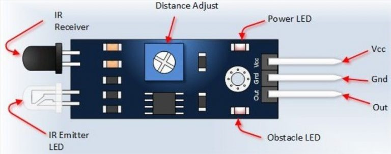
Calibrating the IR Obstacle Sensor is essential at the beginning. Notice that the sensor module has two LEDs: one Power LED and one Obstacle LED. The Power LED will remain lit when power is supplied to the module. Additionally, there is a variable POT. You need to rotate the POT to calibrate the sensor. Adjust the POT so that the Obstacle LED lights up when something is in front of the sensor and remains off when nothing is in front of it. The allowable distance range for this sensor is 2–60 cm. By adjusting the POT, you can set the maximum distance within the 2–60 cm range that the sensor will detect objects.

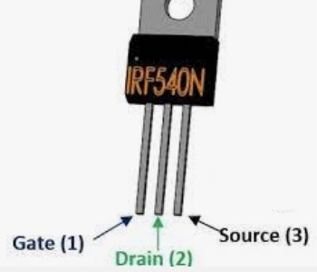
IRF540N pinout
Why use MOSFET in this project?
The solenoid door lock we will use operates at 12 volts, but Arduino’s output voltage is 5 volts. Therefore, you cannot directly switch the door lock using Arduino. We will use a MOSFET to switch the door lock. The IRF540N MOSFET will be used, which is an N-channel MOSFET. The pinout of this MOSFET is as follows:
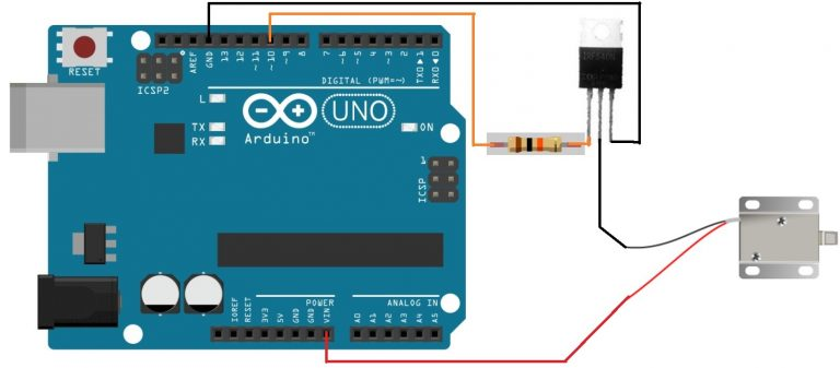
The MOSFET’s Source will be connected to Arduino’s GND pin. The negative side of the door lock will be connected to the MOSFET’s Drain. The positive side of the door lock will be connected to the Vin pin of the Arduino. The Arduino will be powered by a 12V, 3A adapter. A 10K ohm resistor will be connected between a digital pin of the Arduino and the base of the MOSFET. When this pin goes HIGH, current will flow to the MOSFET base, causing the Drain and Source to short, and the door lock will open.
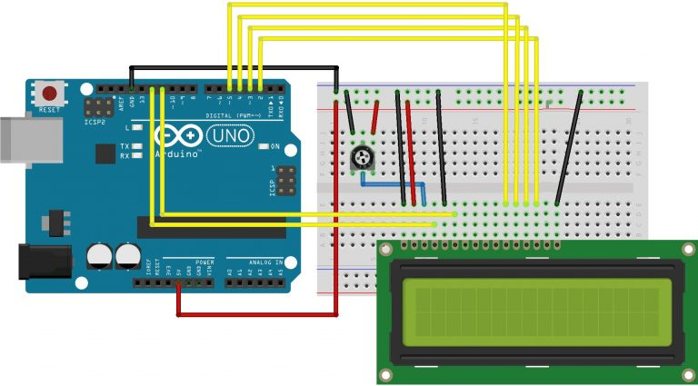
Circuit Diagram and Connection Chart:
| Arduino UNO-R3 | DC Door Lock | IRF540N |
| 10 | 10K resistor in series with G | |
| GND | S | |
| GND | D | |
| Vin | VCC |
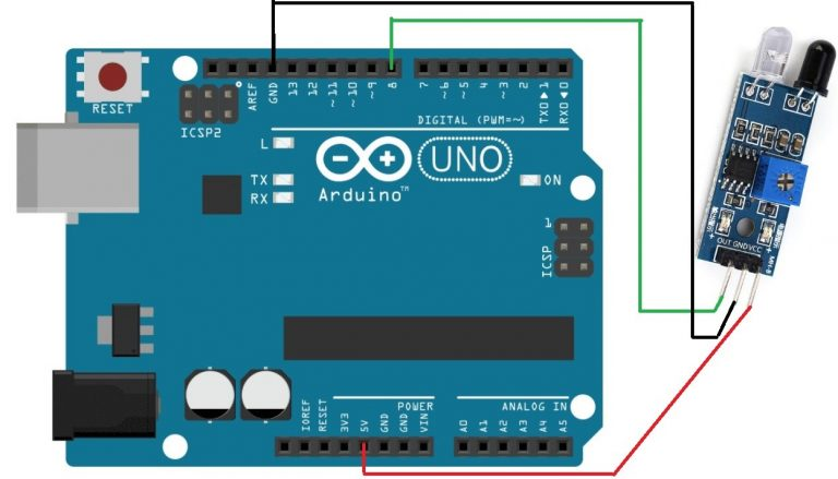
| Arduino UNO | IR Obstacle Sensor |
| VCC | + |
| GND | – |
| 8 | Output |
| Arduino UNO- R3 | LCD |
| GND | VSS,K,1st pin of volume POT |
| 5V | VDD,A, 2nd pin of volume POT |
| V0,3rd pin of the volume POT | |
| GND | RW |
| 12 | RS |
| 11 | E |
| 5,4,3,2 | D4,D5,D6,D7 |

#include <LiquidCrystal.h>
// constants won't change. They're used here to set pin numbers:
const int sensorPin = 8;     // the number of the sensor pin
const int dooorlockPin =  10;      // the number of the dooorlock pin
const int rs = 12, en = 11, d4 = 5, d5 = 4, d6 = 3, d7 = 2;
LiquidCrystal lcd(rs, en, d4, d5, d6, d7);

// variables will change:
int sensorState = 0;         // variable for reading the sensorpin
void setup() {
  // initialize the singnal pin as an output:
  pinMode(dooorlockPin, OUTPUT);
  // initialize the sensor pin as an input:
  pinMode(sensorPin, INPUT_PULLUP);
  Serial.begin(9600);
   lcd.begin(16, 2);
  // Print a message to the LCD.
  lcd.print("Auto Doorlock!");
  delay(1000);

}

void loop() {
  // read the state of the sensorpin:
  sensorState = digitalRead(sensorPin);

  // check if the there is somebody in front of the sensor. If it is, the dooorlockPin is Low:
  Serial.println(sensorState);
  delay(100);
  if(sensorState==LOW)
  {
    digitalWrite(dooorlockPin,HIGH);
    lcd.clear();
    lcd.print("Door opened!");
  }

  else
  {
    digitalWrite(dooorlockPin,LOW);
    lcd.clear();
    lcd.print("Door closed!");
  }
}
Test:
If no one is in front of the sensor, the lock will remain closed.
The LCD will display a message indicating that the door is closed.
In the next test, if someone comes in front of the sensor, the lock will open. Please see the image below:

In this way, we can create an Automatic Door Lock and install it on the door. We have mentioned the necessary components and program, which will allow you to easily create one as well.
How does the IR obstacle sensor detect someone in front of the door?
The IR obstacle sensor works by emitting infrared light and detecting reflections from nearby objects. When someone stands in front of the sensor, the reflected light is detected, and the sensor’s output pin gives a LOW signal, triggering the Arduino to open the door.
What is the maximum detection range of the IR obstacle sensor?
The detection range of the IR obstacle sensor can be calibrated between 2 cm and 60 cm using the variable resistor (POT) on the sensor module. You can adjust the sensor to detect objects within your desired range.
Why is a MOSFET used in this project?
The MOSFET is used to control the solenoid door lock, which requires a higher voltage (12V) than the Arduino’s output (5V). The MOSFET acts as a switch, allowing the 12V power to flow to the lock when the Arduino signals it to open the door.
What happens if no one is in front of the sensor?
If no one is detected by the IR sensor, the output remains HIGH, and the Arduino keeps the door lock closed. The LCD display will show a message indicating that the door is closed.
Image & content Inspired from techshopbd
