

The construction of a transformer is key to its function in electrical systems, enabling the transfer of electrical power between circuits through electromagnetic induction. A transformer is made up of several vital components, including the core, windings, and insulating materials, each contributing to its ability to step up or step down voltage efficiently. Understanding the construction and working principles of transformers is essential for grasping how they operate in modern power systems. This article will explore the fundamental aspects of transformer construction and the importance of its components in regulating voltage and current.
Construction of Transformer
A transformer is a stationary device that increases or decreases the AC supply voltage depending on the current. Simply put, a transformer is an electronic/electrical device that takes in electric power as input and also provides electric power as output, but there is no physical wire connection between them.
Study smarter with VoltageLab
Built for electricians, apprentices, and electrical engineers who want faster practice and better exam prep.
⭐️ Join thousands of electricians upgrading their skills
A transformer is generally composed of the following parts:
- Tank
- Core
- Winding
- Transformer Oil
- Conservator
- Breather
- Tap Changer
- Buchholz Relay
- Radiator and Cooling Tubes
- Bushing
- Drain Valve
- Explosion Vent
- Pressure Relief Valve
- Earth Point and Others.
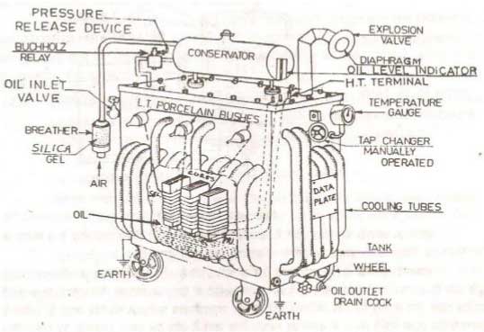
Tank:
The transformer tank is a cylindrical container made of steel. Inside it, the core and windings are located. The transformer tank contains a type of oil that immerses the winding and core. A weatherproof gasket is attached to the top of the tank. The core is anchored to the bottom of the tank.
Core:
The transformer core acts as support. It also serves as a low-reluctance path for the flux generated in the magnetic circuit. The steel frame around which the winding is wound is called the core. The use of a steel core allows the magnetic flux generated on the primary side to easily link with the secondary side.
The core is made up of laminated iron or steel sheets. Each sheet is insulated with a thin layer of varnish or insulation.
The primary reason for using metal sheets is their high magnetic permeability and relatively low hysteresis loss. Laminated sheets reduce eddy current loss. The core’s dimensions depend on several factors (such as voltage, current, frequency). The size of the core is directly proportional to copper loss and inversely proportional to iron loss. Reducing the core size decreases the amount of iron, thus reducing core loss while increasing copper loss.
Winding:
A transformer consists of two main windings: primary and secondary. Usually, these coils are made of super-enameled copper wire. There is no electrical connection between these two windings; rather, they are magnetically connected.
Primary winding is typically connected to the supply, and secondary winding is connected to the load. These two windings are attached to opposite arms of the magnetic core. The coils are well insulated from each other and the core to prevent any electrical connection between them. The voltage difference between the primary and secondary windings depends on the number of turns in the primary (NP) and secondary windings (NS).
A transformer that increases the voltage in the secondary is called a step-up transformer. In a step-up transformer, the number of turns in the secondary coil is greater than that in the primary coil. Conversely, a transformer that reduces the voltage is called a step-down transformer, where the number of turns in the secondary coil is less than that in the primary coil.
Transformer Oil:
Mineral oil is used in the tank and conservator. This oil is primarily used for insulation and cooling the windings.
Conservator:
The conservator stores transformer oil. It is a metal cylindrical drum attached to the top of the transformer, which is sealed to prevent any external elements from entering. The oil level in the conservator is typically kept at half of its height, allowing the oil to expand as the temperature increases. One end of the conservator is connected to the main tank through a pipe.
As the oil heats and cools, its volume changes. A drum is used on top of the tank to manage this expansion and contraction. This drum is called the conservator.
Breather:
The breather controls the moisture content of the transformer oil. When the transformer oil heats up, its volume increases, creating pressure in the conservator. To reduce this pressure, air is allowed to flow into the tank. The breather ensures that this air remains moisture-free. The breather is a cylindrical container filled with silica gel, which absorbs the moisture in the air.
Tap Changer:
The transformer output voltage depends on the input voltage and load. The output decreases under load and increases without load. A tap changer is used to control this voltage variation. Tap changers can be either on-load or off-load.
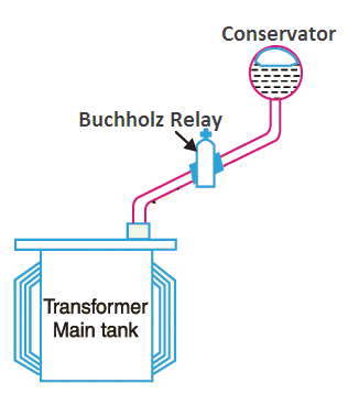
Buchholz Relay:
The Buchholz relay is a protective device used to detect internal faults in a transformer. It is used in transformers where the winding is immersed in oil. It is installed in the connection pipe between the main tank and the conservator. When an internal fault occurs, the transformer oil breaks down and produces hydrogen gas. If the amount of gas is small, the alarm connected to the Buchholz relay sounds.
Radiator and Cooling Tubes:
Radiators are used to cool the transformer oil. The transformer is equipped with multiple cooling tubes. As the oil temperature rises, the hot oil flows upwards in the tank and passes through the cooling tubes from top to bottom. The cooling tubes are in contact with air, which absorbs the heat and cools the oil. Based on how the oil circulates, the cooling system can be of two types:
- Natural Cooling System: The transformer oil flows naturally through the cooling tubes.
- Forced Cooling System: An external pump is used to circulate the transformer oil.
Bushing:
The terminals of the windings used in transformers are brought outside the tank through bushings. These bushings connect the primary coil to the AC source and the secondary coil to the load. The bushings are long, porous insulators made of porcelain and are mounted on top of the transformer tank. There are two types of bushings used in transformers:
- High voltage bushing
- Low voltage bushing
Drain Valve:
The transformer oil is drained out of the tank through a drain cock for testing or refining purposes. The pipe of the drain valve is welded to the transformer tank. This valve is T-shaped and requires a special key to open it.
Expulsion Vent:
The expulsion vent is a bent pipe with an aluminum diaphragm installed on top of the transformer. It is used to reduce the high pressure inside the tank in case of a major fault in the transformer.
Study smarter with VoltageLab
Built for electricians, apprentices, and electrical engineers who want faster practice and better exam prep.
⭐️ Join thousands of electricians upgrading their skills
Pressure Relief Valve:
The pressure relief valve is used to reduce the high pressure that occurs in the transformer during a fault. It is a spring-controlled device installed on top of the main transformer tank. When the internal pressure increases, this valve opens to release the excess pressure.
Earth Point:
To protect the transformer from various accidents, its body has two earth points. These earth points are connected to the ground.
Transformer Structure with Diagram:
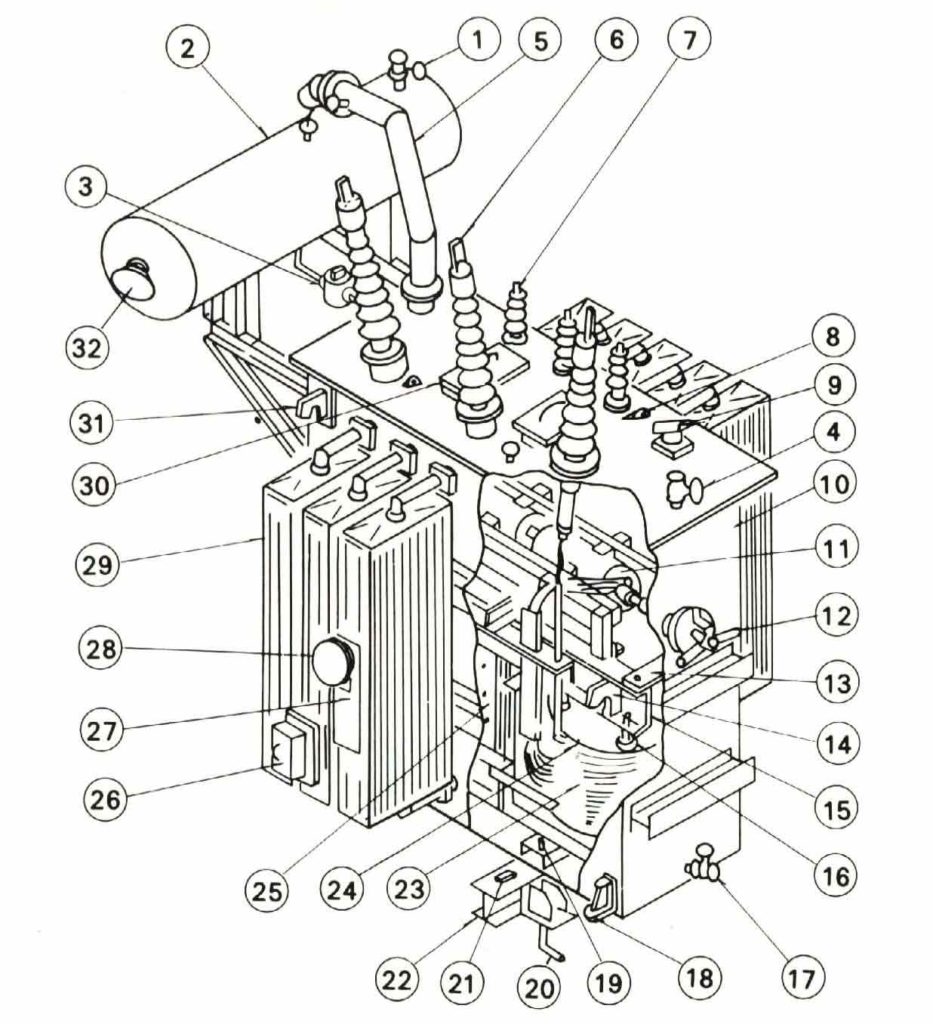
| 1 | Oil filter valve | 17 | Oil drain valve |
| 2 | Conservator | 18 | Jacking boss |
| 3 | Buchholz relay | 19 | Stopper |
| 4 | Oil filter valve | 20 | Foundation bolt |
| 5 | Pressure-relief vent | 21 | Grounding Terminal |
| 6 | High-voltage bushing | 22 | Skid base |
| 7 | Low-voltage bushing | 23 | Coil |
| 8 | Suspension lug | 24 | Coil pressure plate |
| 9 | B C T Terminal | 25 | Core |
| 10 | Tank | 26 | Terminal box for protective device |
| 11 | De-energized tap changer | 27 | Rating plate |
| 12 | Tap changer handle | 28 | Dial thermometer |
| 13 | Fastener for core and coil | 29 | Radiator |
| 14 | Lifting hook for core and coil | 30 | Manhole |
| 15 | End frame | 31 | Lifting hook |
| 16 | Coil pressure bolt | 32 | Dial type oil level gauge |
FAQ
1. What are the key components involved in the construction of a transformer?
The primary components include the core, windings (primary and secondary), transformer oil, conservator, Buchholz relay, tap changer, radiator, and cooling tubes. Each of these parts plays a critical role in the overall operation of the transformer.
2. How does the core of a transformer contribute to its functionality?
The core is made of laminated steel sheets that minimize energy losses due to eddy currents. It provides a low-resistance path for the magnetic flux, which is essential for transferring electrical energy between the primary and secondary windings.
3. What role do the windings play in a transformer?
The windings, made of copper or aluminum, carry the input and output current. The primary winding receives electrical power, while the secondary winding delivers power to the output circuit, with voltage being stepped up or down depending on the transformer type.
4. Why is transformer oil important, and what is its function?
Transformer oil is crucial for both insulation and cooling. It helps dissipate the heat generated during operation and insulates the internal components to prevent electrical breakdowns.
Practice more with electrical quizzes
NEC · BS7671 · AS/NZS · CEC · DIN VDE
