
An Astable Multivibrator Circuit is a fundamental electronic configuration that generates continuous square waves without external triggering. Using a 555 Timer IC, you can easily build this circuit to create a stable oscillation that finds applications in timers, pulse generators, and LED flashers. In this guide, we will explore the components and steps required to build an Astable Multivibrator Circuit with a 555 Timer IC, providing an excellent learning opportunity for both beginners and experienced electronics enthusiasts.
The use of the 555 Timer IC is significant when working with electronics devices and various electronics projects. So today, we will create an astable multivibrator circuit using this timer IC.
Required Materials
- Battery (6v-12v) – 1
- 555 Timer IC – 1
- Capacitor 100uf – 1
- Capacitor 10nf – 1
- Resistor (10k ohm) – 1
- Resistor (1k ohm) – 1
- LED – 1
- Project Board – 1
Astable Multivibrator Circuit Diagram
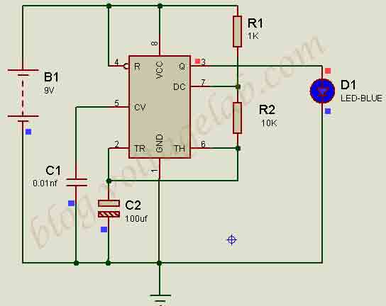
Complete the circuit connection according to the above circuit diagram.
Study smarter with ElectricPal
Built for electricians, apprentices, and electrical engineer who want faster practice and better exam prep.
Available for Android and iPhone.
555 Timer Pin Configuration
The 555 Timer has 8 pins.
- Ground
- Trigger
- Output
- Reset
- Control Voltage
- Threshold
- Discharge
- +VCC
PIN NO: 01: This is the Ground pin. It should be connected to the ground of the circuit.
PIN NO: 02: This is called the Trigger pin. Similar to the Threshold pin, the output can change depending on whether the input voltage is higher or lower than the reference voltage.
PIN NO: 03: This is the Output pin. Two types of outputs (+Vcc and 0V) are possible on the output pin. The maximum output current is 200mA. It’s worth mentioning that the output signal of the 555 IC comes from an internal R-S flip-flop, so only digital output (+Vcc and 0V) is available.
The trigger (2), threshold (6), and control (5) pins of the 555 IC can be considered input pins.
PIN NO: 04: This is the Reset pin. It is an Active Low pin, meaning to reset the 555 IC, this pin should be set to Low (0V). If not, it should always be kept High (+Vcc).
PIN NO: 05: This is the Control pin. It can control the reference voltage of the Threshold (6) and Trigger (2) pins. If not needed, it is grounded with a small capacitor (1nF/10nF).
PIN NO: 06: This is the Threshold pin. By default, its reference voltage is two-thirds of Vcc. For example, if the Vcc pin has 9V, the threshold voltage will be 9 × (2/3) = 6V.
PIN NO: 07: This is the Discharge pin. When the output pin is Low (0V), an internal electronic switch connects the Discharge pin to the ground. When High (+Vcc), the switch disconnects the Discharge pin from the ground.
PIN NO: 08: This pin provides power to the 555 IC. It can supply between 4.5V and 16V.
Operation
We have created a multivibrator circuit using the 555 Timer.
Multivibrator
An electronics device capable of generating non-sinusoidal waves such as square waves, sawtooth waves, or rectangular waves is called a multivibrator.
Astable Multivibrator
A multivibrator that has two temporary stable states (OFF and ON) and automatically generates square waves without external triggering pulses is called an astable multivibrator.
Circuit Analysis
The 555 Timer plays a key role in this circuit. The pin operations are as follows:
Pin 1: Ground: This pin connects the circuit to the ground.
Pin 2: Trigger: When the input voltage drops below one-third (if input voltage is 9V, trigger voltage will be 9/3= 3V), the output turns on.
Pin 3: Output: An LED is connected to this pin.
Pin 4: Reset: This pin is connected to pin 8 and remains deactivated.
Pin 5: Control Voltage: A capacitor is required to control the voltage. Changing the capacitor’s value will control the LED blinking time.
Pin 6: Threshold: When the input voltage is two-thirds of Vcc (6V if input voltage is 9V), the output turns off.
Pin 7: Discharge: When the input voltage is low, the capacitor discharges.
Note: Resistors connected to pins 6 and 7 assist in discharging the capacitor, forming a voltage divider.
Pin 8: +Vcc: Provides voltage input.
Note: The voltage and current ratings of the 555 Timer are: +4.5V to +16V and 200mA.
Precautions:
- Do not apply a voltage higher than the rated voltage to the 555 Timer.
- Do not apply AC voltage to the 555 Timer.
- Ensure all components are properly connected during circuit assembly.
Video
That’s it for today, friends. If you encounter any issues while building the circuit, please let us know in the comments.
What is an astable multivibrator circuit?
An astable multivibrator is an electronic circuit that generates continuous square wave oscillations without requiring an external trigger. It operates as a free-running oscillator, switching between two unstable states, making it useful for generating clock pulses, flashes, and other timing functions.
How does an astable circuit work?
An astable circuit works by continuously switching between high and low voltage states, generating a square wave output. This is achieved by charging and discharging capacitors in the circuit, which causes the output to oscillate at a frequency determined by the resistors and capacitors used.
How to design an astable multivibrator?
To design an astable multivibrator, you need a 555 Timer IC, two resistors, and a capacitor. The resistors and capacitor determine the frequency and duty cycle of the oscillation. By selecting appropriate values for these components, you can control the timing and waveform of the output.
What is the output waveform of an astable multivibrator?
The output waveform of an astable multivibrator is a continuous square wave. The frequency and duty cycle of the square wave depend on the values of the resistors and capacitor in the circuit.
What is called a multivibrator?
A multivibrator is a type of electronic circuit used to implement two or more states of operation, usually generating square waveforms. It can operate in different modes: astable (free-running), monostable (one-shot), or bistable (flip-flop), depending on its configuration.
What are the applications of multivibrators?
Multivibrators are used in a variety of applications, including signal generation, pulse shaping, timing circuits, LED flashers, frequency dividers, and digital clocks. They are commonly used in electronics projects that require periodic or timed signals.
Read More: Circuit Diagram of Monostable Multivibrator Circuit
Ready to pass your exam?
Join thousands of electricians and apprentices using ElectricPal to study smarter and score higher.
Free to download · Available for Android and iPhone
