
Clipping and clamping circuits are essential topics in electronics, playing crucial roles in shaping and controlling signal waveforms. Clipping circuits modify the amplitude of a waveform by “clipping” parts of it, while clamping circuits fix the signal to a specific DC level without altering its shape. In this article, we will explore the principles, types, and practical applications of both clipping and clamping circuits, providing a detailed understanding of how they work in electronic systems.
Clipping and clamping are common topics in electronic circuits. This article attempts to discuss several questions and answers related to clipping and clamping.
Clipping Circuit
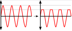
Clipping is an English word meaning cutting or trimming. The electronics circuit that clips or cuts off certain parts of the input sine wave to create a new wave shape is called a clipping circuit.
This type of circuit is mainly of three types:
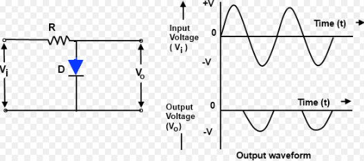
1. Positive Clipper: This clips the positive half cycle of the input voltage completely to create the output.

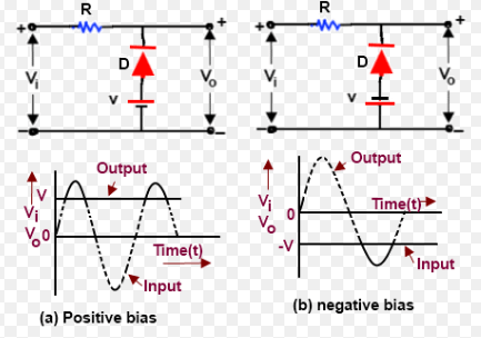
2. Biased Clipper: This clips a specific part of the positive or negative half cycle of the input signal to generate the output.
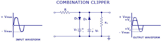
3. Combination Clipper: This clips a specific part of both the positive and negative half cycles of the input signal to create the output.
Clamping Circuit
Clamp is an English word meaning to hold or fix. A clamping circuit is a circuit that holds the positive or negative peak of the input signal at a predetermined value on the desired DC level. It is also called a DC restorer because the output in this circuit is obtained at a specific DC level.
This type of circuit adds the DC part of an AC or any other signal without changing the waveform’s shape. Clamping circuits are mainly of two types:

1. Positive Clamping:
This is a type of circuit that holds the positive peak of the input wave at a predetermined value on the desired DC level.
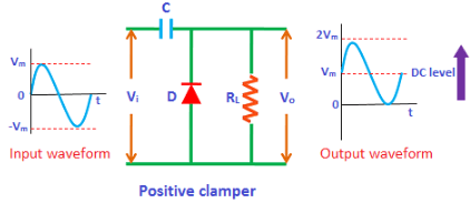
For Negative Cycle:
When a sine wave is applied to the input, during the negative cycle, the diode is forward biased. In this condition, current flows through the diode, allowing the capacitor to charge up to the input voltage, Vm. The capacitor charges with the inverse polarity of the input voltage and holds the charge as long as the diode remains forward biased.
For Positive Half Cycle:
During the positive cycle of the input sine wave, the diode is reverse biased, allowing the input current to flow directly to the output RL. As the capacitor discharges, the output voltage becomes the sum of the capacitor voltage (Vm) and the input voltage (Vm).
Thus, Vm + Vm = 2Vm
The peak-to-peak amplitude of the input signal is 2Vm, and the same applies to the output signal.
2. Negative Clamping:
This is a clamping circuit that holds the negative peak of the input wave at a predetermined value on the desired DC level.
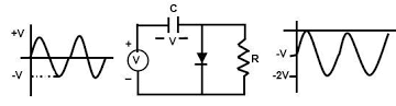
For Positive Cycle:
During the positive half cycle, the diode remains forward biased, so no signal passes through the output (R). The capacitor charges at the peak voltage of the input, (-Vm), with inverse polarity. It retains the charge until the diode remains forward biased.
For Negative Cycle:
During the negative half cycle, the diode is reverse biased, so the input signal passes directly to the output (R).
As the negative half cycle begins, the charged capacitor discharges, and the output voltage becomes the sum of the capacitor voltage (-Vm) and the input voltage (-Vm).
Thus, -Vm – -Vm = -2Vm
As a result, the output signal shifts downward.
Where Are Clipping and Clamping Circuits Used?
Clipping circuits are used in:
- Radar
- TV Transmitter
- TV receiver
- Oscilloscope
- TV camera
- Computer
- VCP, VCR, and other devices.
Clamping circuits are used in:
- FM radio receiver
- Digital Telegraphy system
- Hybrid radio receiver
- Oscilloscope
- TV, and other devices.
What is a clamper circuit diagram?
A clamper circuit diagram represents the configuration of electronic components used to “clamp” a signal to a specific voltage level. The basic components include diodes, capacitors, and resistors, which work together to shift the waveform up or down without altering its shape.
What are the applications of a clamper circuit?
Clamper circuits are used in various applications, including TV receivers, voltage level shifters, signal restoration, and oscilloscope displays. They are essential in adjusting the DC level of signals in communication systems and waveform generators.
How does a clamper circuit work?
A clamper circuit adds a DC component to an AC signal, shifting the entire waveform either upwards or downwards. This is achieved by using a diode, capacitor, and resistor network that charges and discharges the capacitor, ensuring the waveform is clamped to the desired voltage level.
What is clipping in a circuit?
Clipping in a circuit refers to the process where portions of a waveform are removed or “clipped” when they exceed a certain voltage level. This limits the amplitude of the signal, preventing it from going beyond a set threshold.
What is the clipper circuit?
A clipper circuit is an electronic circuit that limits or clips the amplitude of a signal without distorting the rest of the waveform. It can be designed to clip either the positive, negative, or both halves of the input signal, depending on the configuration.
What is the principle of a clamping circuit?
The principle of a clamping circuit is to shift the entire waveform to a new DC level, without altering its shape. It accomplishes this by introducing a DC component to the signal, ensuring the waveform “clamps” to a new reference voltage, typically through the action of a diode and capacitor.
What are the applications of a clamping circuit?
Clamping circuits are commonly used in television receivers, voltage level translation, signal restoration, and improving signal fidelity in communication systems. They are vital in circuits where maintaining or adjusting the DC reference level is essential.
What is the theory of clipping and clamping circuits?
The theory behind clipping and clamping circuits lies in their ability to manipulate the amplitude and DC level of signals. Clipping circuits remove parts of the waveform that exceed predefined limits, while clamping circuits add a DC level to shift the waveform. Both circuits are fundamental in waveform shaping and signal conditioning in electronic systems.
Read More:
