
Diode testing, transistor testing, and troubleshooting methods are fundamental skills for anyone working with electronic components. Proper identification of diode legs (anode and cathode) and transistor terminals (base, emitter, and collector) is essential for accurate circuit design and maintenance. This guide provides a comprehensive approach to identifying, testing, and troubleshooting diodes and transistors, ensuring that these critical components function optimally in various applications. By mastering these techniques, you can enhance the reliability and performance of your electronic projects.
Table of Contents
Diode and Transistor Leg Identification, Testing, and Troubleshooting Methods
Diode Leg Identification / Anode-Cathode Identification Method
Identifying the legs of a diode or determining the anode-cathode is quite easy. Anyone can recognize which end is the anode and which is the cathode just by looking at the diode. Simply observe the image below carefully.
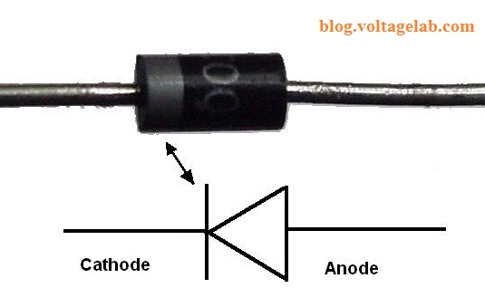
The part of the diode with the white stripe is the cathode, and the part without the white stripe is the anode, as shown in the image.
Method for Testing if a Diode is Good or Bad:
Testing a diode is as easy as pie. Anyone can do it with a little attention. You can use either a digital or analog multimeter to test a diode. However, make sure that your digital/analog multimeter has a diode/resistance selector.

Most multimeters available in the market have diode and resistance options. Using the ohm or resistance measuring option of the meter, you can measure the diode in this way. Here are the steps:
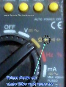
- First, set the multimeter’s selector to the diode/resistance mode. An image is provided below for better understanding.
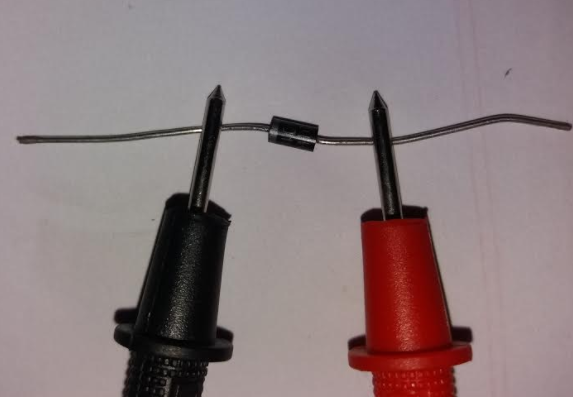
- Now, we will perform a forward test on the diode, meaning we will connect the positive probe of the multimeter to the anode and the negative probe to the cathode, as shown in the image.
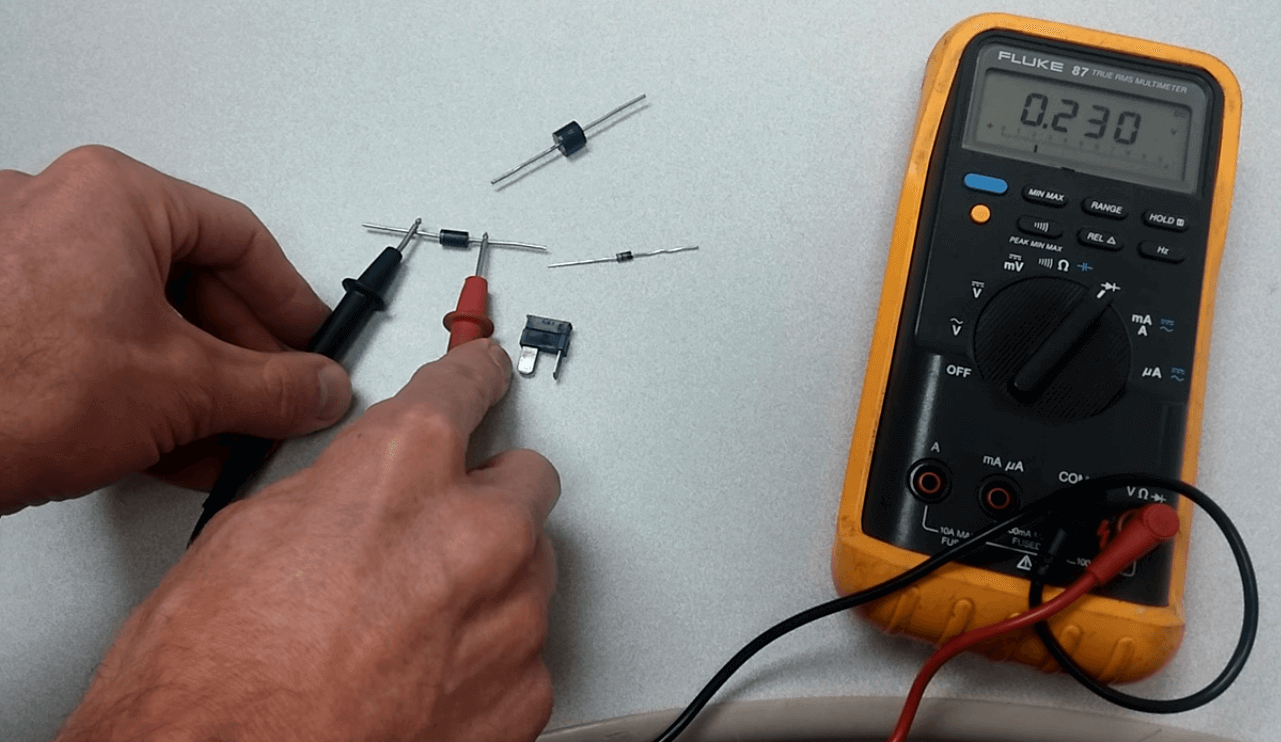
Here, a reading of 0.23v is shown, indicating that the diode will drop approximately 0.23 volts under no-load conditions, and very little current (1mA/2mA) will flow through the diode in this state.
In the case of silicon diodes, the voltage drop will be up to 0.7 under load, and for germanium, it will be up to 0.3.
If measured with an ohmmeter, it will show a resistance, which is very low. This is dynamic resistance that decreases as the current flowing through the circuit increases, which is the basic characteristic of a diode.

Note: In the case of an analog multimeter, the probes need to be reversed, meaning the black probe should be placed where the red probe was, and the red probe where the black probe was.
However, some analog multimeters are now being made following digital multimeters. In that case, refer to the manual to determine the correct probes.
- Now, we will perform a reverse test on the diode, which means we will do the opposite of the previous process. This means connecting the red probe to the cathode (the white-striped part of the diode) and the black probe to the opposite side (anode).
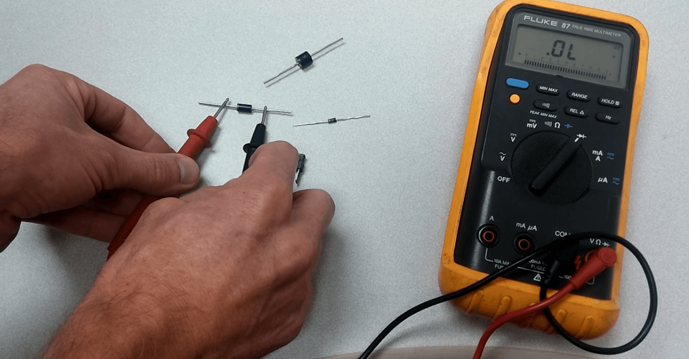
The multimeter display in the image shows a value of 0, meaning no voltage is flowing, which is normal since a diode is a unidirectional device, so this diode is considered good. When measured with an ohmmeter, no value will be shown in this case.
Method to Identify Transistor Legs / Easily Determine the Base:
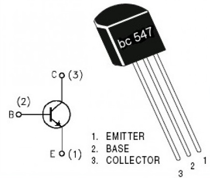
If we know the model number of the transistor we buy from the market, we can easily search on Google to find out the transistor’s base, emitter, and collector.
However, there is an issue with this simple method: different manufacturers might have different pinouts for the same transistor package. You can understand this by looking at the image below:
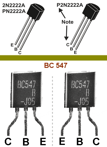
In the image, we can see that the BC547 transistor and the 2N2222 transistor have different pinouts. For beginners, this can be a big problem, and if the transistor is connected incorrectly, it won’t work.
In this case, I recommend hobbyists always use a multimeter to identify the transistor legs. Not just for transistors, but before working with any equipment that can be tested, make sure to test it first.
We will determine the base, emitter, and collector for both NPN and PNP transistors. To make this task easier, we will first use a multimeter to identify the base of the transistor. Then, we will determine the collector and emitter. For beginners, we have described the process step by step.
Simple Method to Identify the Base of an NPN Transistor
Base Identification
- Set the selector on the multimeter to diode/ohm, just like in the previous case with the diode.
- Now, assume one of the three terminals of the transistor to be the base and test it.
- Connect the positive probe (red) of the multimeter to the assumed base terminal and the negative probe (black) to the other two terminals, one at a time.
- Repeat the same test for the other two legs of the transistor, assuming each as the base. Look at the image below:
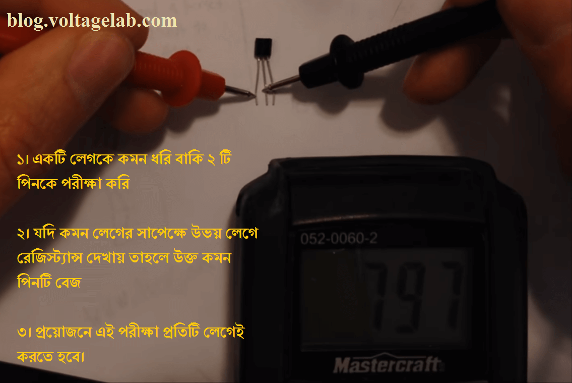
- If there is some resistance between both legs, it means the common leg is the base of the transistor. If it is short, the resistance will show as zero.
Simple Method to Identify the Base of a PNP Transistor
Base Identification
- As before, set the selector knob of the multimeter to measure resistance/diode.
- Now, assume one of the three terminals of the transistor as the base and test it as a PNP transistor.
- Connect the negative probe (black) of the multimeter to the assumed base terminal and the positive probe (red) to the other two terminals, one at a time.
- Repeat the same test for the other two legs of the transistor, assuming each as the base.
- If there is some resistance between both legs, it means the common leg is the base of the transistor. If it is short, the resistance will show as zero.
Determining the Collector and Emitter for Both Transistors
If you can identify the base, this task becomes quite easy. We can easily identify them using a digital multimeter by setting the selector knob to diode/resistance mode.
- Compare the resistance of both legs from the base using a multimeter.
- The leg with the higher resistance will be the emitter of the transistor.
- The leg showing lower resistance will be the collector.
Identifying this with an analog multimeter is quite challenging and difficult because the resistance value is only a few ohms. As a result, the needle movement on an analog multimeter is not very noticeable.
Moreover, modern analog multimeters have a dedicated option for testing transistors.
The results from testing the transistor we used:
- After placing the red probe on one end of the transistor (middle leg), we obtained resistance on the other two legs, indicating that this is an NPN-type transistor and the middle leg is the base.
- Compare the readings obtained by holding the multimeter from the base to the left leg and from the base to the right leg.
- According to our values: Base to left leg = 649, and Base to right leg = 655. Thus, the left leg is the collector, and the right leg is the emitter.
Testing Method to Determine if a Transistor is Good or Bad:
If the needle of the meter does not move with any of the other two leads, the transistor is open and defective. If the needle moves for all tests, the transistor is shorted and defective. If the needle moves slightly in any one test, the transistor is leaky and defective.
